|
How To Perform A Simple Voltage Test On Circuit Board
Well, I’ve got many emails asking me to show them how to perform a voltage test for troubleshooting purposes. Although many of them already know how to test electronic components and be able to repaired electronic equipment, learning some simple voltage test could help them to diagnose the fault even faster. In this article, I’m assuming that you have some electronic repair knowledge and understood how SMPS work and etc. Alright let’s start!
Performing Voltage Test On Resistor
In a circuit board there are lots of electronic components particularly the resistors and you wish to place your test probe on some of the resistors test points. The question is where should you place the test probe and what voltage should you expect from the test point? It is quite confusing as there are so many resistors on the board. In order to solve this problem you must first understand how that equipment works. For example if you are in TV repair, you must know how a TV works and be able to know the individual section of the TV. We cannot simply put our test probe to any test points that we like.
If the complaint is one horizontal line then you can expect the fault in the vertical section. Again, how do we know where the vertical section is and how to identify vertical section? The answer is in the TV repair book as most of the TV repair book will explain about how a TV works and show you with the help of photos how a vertical section look like. In other words, if you wish to repair a DVD player then get a book that explain how a DVD works and study the photos of the DVD player section.
About the one horizontal line problem in TV, you can also suspect the switch mode power supply because if there is no supply to the vertical section, obviously the vertical section would not work thus producing a straight horizontal line across the screen.
Now assuming you have identified the vertical section, you need to perform the voltage test on the Vertical IC, what is the next step you should do? Simple, get the schematic of the vertical IC and find out the supply voltage (VCC) pin. Once you have identified the pin now turn On the power and place your red probe to the VCC pin and black probe to cold ground. Read the voltage and if it is good then perform the waveform test which I don’t cover in this article. If the voltage is low or missing then you got a clue that either the supply line has problem or the vertical IC itself or corresponding components have problem that pulling down the voltage.
Here is the way on how you can perform the voltage test along the supply line. Move the red probe backward till you meet a resistor (usually this is a low ohm resistor or a protection resistor- 0.22 to 1 ohm). If you still do not get the right voltage then I suggest that you lift up the resistor and recheck the voltage again or you can directly test the ohm value of the resistor.
If the voltage is good then suspect the resistor already have an open circuit. Similarly this voltage test can be done on other type of circuit like the CPU, EEPROM, COLOR, HORIZONTAL and even in Power supply circuit.
Note: A bad filter cap (high ESR value) along the supply line to the vertical IC could cause the voltage to become low.
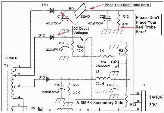
The above test is about tracing voltage backward and what if you need to trace it forward? Same principle, understand the circuit function and place the red probe onto the right place. SMPS produce DC output voltages and you can follow the line till you reach the last point of the circuit. For example, tracing the B+ voltage line till flyback transformer pin and you may pass through a resistor and that resistor is usually a low ohm resistor (0.22 to 1 ohm). Since this is a low ohm resistor you can expect the voltage to be same or slightly drop a bit after the resistor. If you get zero output voltage then you will automatically know that the resistor had an open circuit.
For your information not all circuit are created the same. For example, the Monitor B+ circuit that have boost and buck circuit. If you trace from the DC output to the Boost circuit then you have to expect an increase in DC voltage at the output of the circuit. If you are tracing the Buck circuit then expect a lower voltage at the output of the circuit. Isn’t it important to understand how a circuit work (I mean CRT Monitor circuit) if you are in the CRT Monitor repair?
Assuming if you are tracing a circuit like the start up resistor in SMPS and meet a 100 K Ohm or higher resistor value then expect it to drop even more may be from 300 VDC to 16 VDC!
Now, not all DC voltages that passes through a resistor will drop in voltage, some resistors are directly connected to ground like the bleeder resistor. If you follow the DC output line and trace after the resistor you will get ZERO volt.
It is understood that any point going to ground must be zero volt. In other words, not only you must understand how a circuit work, you are also required to know the resistor value and where the resistor is connected if you want to perform the voltage test.
Performing Voltage Test On Coil/Inductor
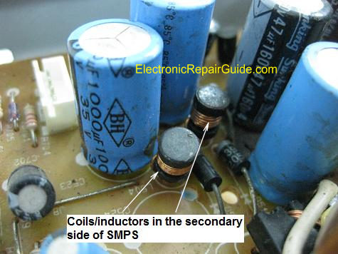
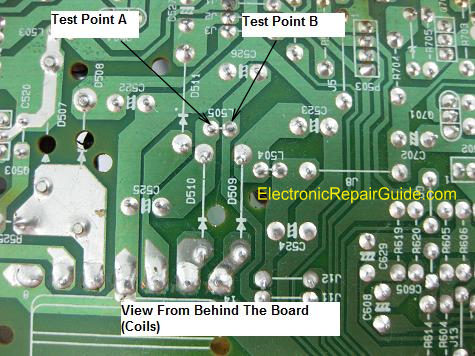
If you are troubleshooting the secondary side of SMPS, you will sometimes see some small coil/inductor along the DC output line as shown from the photo. The function of these coils is to allow DC to flow through it while restricting AC current flow. Due to the value (in microhenry) too small in fact by replacing with a wire have no effect on the DC output and to the equipment. Testing the voltage before and after the coil is just like when you want to test the resistor. Place your red probe before (test point A) and after the coil (test point B) and black probe to cold ground and you should expect the same DC output voltage. If you get the input voltage but no output voltage then suspect the coil have developed an open circuit. If you do not wish to perform voltage test on coil you can always use an ohmmeter to test the coil resistance.
Conclusion- Understand how electronic equipment work and be able to identify each of the section of the equipment will give you a great advantage of solving a problem fast by using the simple voltage test method. What you need to do is to practice more on a working board (with power On) and write down all the critical test points of that equipment so that in the future if any of those equipment come in for repair you will roughly have an idea on what are the voltages to expect on those section (test points) even without have to refer to any schematic diagrams. Have fun in repairing and all the best to you!
Click here to learn how you can become a Professional in Testing Electronic Components
Click here to learn how you can become a Professional in LCD Monitor Repair
Recommendation:
Recommended Mr Kent Projection Television Repair Membership website-Visit Now!
Recommended Mr Kent LCD TV Repair Membership website-Visit Now!
Recommended Mr Kent Plasma TV Repair Membership website-Visit Now!
|
|


Copyright@ 2006-2014-www.ElectronicRepairGuide.com All Rights Reserved