|
About Optoisolator IC and The Right Way To Test It
Introduction
Optoisolator IC or Optocoupler (board location marked as “IC”) is widely used in many electronic circuits such as in the Power supplies (TV, Monitor, Computer), Modem, Medical Equipment and etc. The Opto-isolator is simply a package that contains both an infrared light-emitting diode (LED) and a photodetector such as a photosensitive transistor, silicone diode, Triac, transistor Darlington pair, or silicon controlled rectifier (SCR) as seen from the photo below. Among all the Optoisolator ICs, the LED/Phototransistor type is the most commonly used in the consumer electronics.
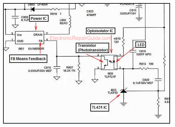
Optoisolator IC allows two circuits to exchange signals yet remain electrically isolated. Let’s take the function of Optoisolator IC (part of error signal feedback) that were found in switch mode power supplies as an example. The phototransistor acts as an output device while the LED acts as an input device. The light generated by the LED is determined by the level and potential of the DC error voltage applied to the LED’s by the error detection circuit. When the LED is emitting light (inside the Optoisolator IC), the phototransistor is conducting. That means if the LED light intensity is great, the phototransistor will conduct even more and vice versa (decreases and increases its resistance proportionally) thus controlling the input to the oscillator in Power IC (through feedback pin as seen from the below figure ).
The Feedback Circuit In SMPS
The end result causes the oscillator’s frequency to change in response to the error signal feedback and alters the drive signal to compensate for the output voltage change. Remember, this comparison/compensation occurs continually and provides a closely regulated output voltage.
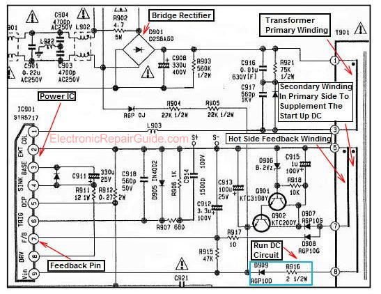
Note: The feedback circuit also provides isolation between the cold ground (LED) side and the hot ground (phototransistor) side of the power supply. In some designs, the error signal feedback is developed from the hot side secondary winding of the power supply and requires no isolation as seen from figure below.
The error signal feedback is developed from the hot side secondary winding
Please observe the Power IC (IC901) pin number 7 written as F/B which means feedback. Tracing backward from this pin, it will lead you to the feedback winding at pin 7 of T901.
If the Optoisolator IC have problems like an open LED or a shorted/leaky phototransistor, the power supply would blink, or produce lower voltage or even shutdown after the power supply is turned “On”.
Beside monitoring the output voltage sampling for regulation and provide ground isolation, the Optoisolator IC circuit in the power supply also provide System control micro for power on/off, Over current protection and energy saving (by shutting down the high voltage) in Monitors if the VGA signal is not connected to the CPU computer. That’s why sometimes you could see more than one Optoisolator IC in a power supply circuit.
Why some power supply does not use Optoisolator IC?
Its all about cost saving. The primary sensing (hot side feedback-figure 3) is cheaper but the output regulation is less accurate. It is used especially for the low end market (low power, low budget). Secondary sensing (the regulation circuit that consist of Optoisolator IC, TL431 IC and some other components) is more expensive but has a higher performance. It is used especially in the medium and high end market.
4 and 6 pins Optoisolator IC
There are 4 and 6 pins Optoisolator IC found in the market which is the most commonly used. There are also Optoisolator ICs that have many pins. No matter how many pins an IC have, always refer it to the datasheet so that you will know what type of photosensitive device used and also how many components in it.
Once you know what type of components and how many components in it then you can use the right way to test it.
Note: Optoisolator ICs can come in dual in line package or in SMD type.
Testing Optoisolator IC
Since there are so many types of Optoisolator ICs in the market thus I could not cover all of it. I’m only showing to you how you can test the one that is commonly used and found in the market which is the LED/Phototransistor type.
1) Set your analog meter (using Sunwa meter) to X10 K ohm. Place your test probes on pin 1 and 2 (measuring the internal LED) and you should get one reading when testing it either way. If you get two readings or no reading at all, then the internal LED have problem and need to be replaced. You can use this method too to test any silicone diode.
2) From the datasheet, you would know which pin is the base, collector and emitter. Now set your meter to X1 Ohm and place the black probe to the base (pin 6) and the red probe to collector and then to the emitter. You should get a low resistance when the red probe touches on the collector and emitter pin. If you do not get any reading or you get only one reading, that means the internal phototransistor have problem. Now, set your meter to X10 K ohm and measure the collector and emitter pin and you should get one high resistance reading. If you get one high resistance reading when testing it either way, that means the phototransistor is good.
Here is one interesting question that I frequently asked by my ERG member “What if there is no reading at all when tested it both ways with the test probes-is the IC bad?”
The answer is you have to confirm it by using another method because certain Optoisolator IC phototransistor has very high ohm of resistance thus the meter can’t get any reading. In order to solve this problem you need to get another similar analog meter.
Connect the two meters in series like a battery. The black probe of one meter is connected to the red probe of another meter. You can joint the probes with the help of an alligator clip. Both meters set to X10 K ohm range to increase the resistance that it can measure. Now, test again the IC with the probes and it should show a high resistance reading. If by using this method and you still cannot get any reading, that means the phototransistor already open circuit.
Assuming if you do not have a spare meter and do not wish to invest on another one you can use a variable DC regulated power supply to check if the Optoisolator IC is functioning well or not. Connect a 330 ohm ¼ watt resistor to pin 1 of the IC, now place the positive supply to the other end of the resistor as shown from the photo below. The negative supply is connected to pin 2. Next, set your analog meter to X10 K ohm, place the black probe to pin 4 (emitter) and red probe to pin 5 (collector).
Turn on the DC power supply and slowly increase the voltage from zero volts to few volts. For a good Optoisolator IC, you could see that the resistance gradually increase or decrease depending on the volt setting. The higher the volt you set, the lower is the resistance. Similarly, the lower the volt you set, the higher is the resistance. If you get an intermittent reading or no reading with this testing method, the phototransistor is considered to have problem.
For your information, the 4 pins Optoisolator IC does not have the base pin but testing is the same. Just place the test probes on collector and emitter pin and follow the above steps. If there are few transistors in a single package IC, you can test the transistor individually.
Note on substitution- By referring to datasheet downloaded from the Internet; you can find equivalent part number for it. The famous 4N35 (6 pins) and PC123 (4 pins) part number can be easily used to substitute on many different types of Optoisolator IC part number. This 4N35/PC123 IC is quite common and can be easily found from any electronic shop.
Conclusion- You can directly replace the Optoisolator IC (since it is cheap) but knowing the right way to check and measure the IC will give you a greater satisfaction especially when the fault can be identified. About checking other types of Optoisolator IC (such as the SCR, TRIAC, Darlington transistor photodetector type), I will leave it to you to come out with your own way of testing. You will be happy if you could find solution to test on such Optoisolator ICs. That’s all for now and hope to send another good article to you next month.
Click Here to Get 24 Best Electronics Repair Articles
Click here to learn how you can become a Professional in Switch Mode Power Supply Repair
Click here to learn how you can become a Professional in Testing Electronic Components
Click here to learn how you can become a Professional in LCD Monitor Repair
Click here to learn how you can find burnt resisto value
Recommendation:
Recommended Mr Steve Cherubino Laptop Repair Videos For Beginners!
Recommended Mr Kent Projection Television Repair Membership website-Visit Now!
Recommended Mr Kent LCD TV Repair Membership website-Visit Now!
Recommended Mr Kent Plasma TV Repair Membership website-Visit Now!
|
|


Copyright@ 2006-2014-www.ElectronicRepairGuide.com All Rights Reserved