Simple Secrets To Speed Up On How To Test Electronic Components-Part IIf you are in the electronic repair line you would know that checking electronic components in electronic boards can take up lots of your time especially if you do not know the short cut way to test it. Many of us when starting in the field of electronic repair check each electronic component one by one by removing it out from the board. This is the right way to test electronic components but it is very time consuming.
For example, if you already confirmed that the power supply section is the main cause of the problem in electronic equipment, you may take about 30-45 minutes to scan through all the electronic components in the section but for some senior or experienced repair technicians, they can check all of the electronic components in less than 15 minutes and accurate too! Wow, that was almost half of the time you spent on checking them.
This is a big different in terms of efficiency of how many equipment you can repaired in a day. In other word, if you can solve a problem fast, you can actually repair more equipment in a day and more profit to you. Wouldn’t it be great if you can have the skills like the super tech? Or you may ask “Is there a way to actually cut short the process of testing electronic components and at the same time produce accurate result? Yes there is, in this article I’m going to show you how you can speed up the process of testing electronic components. Let’s start!
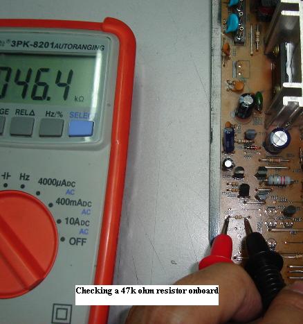
We will start with resistor first. Normally the right way to test a resistor is to desolder out one lead and then measure with digital multimeter (please don’t use analog meter as it won’t show you a precise reading). Do you know that you can actually check a resistor while it still on board? This is true especially when the test voltage output from your digital meter is less than 0.6 volt as it would not trigger the surrounding semiconductors like the transistors, diodes and integrated circuits (IC). If it is more than 0.6 volt then you may not get an accurate result because your meter had triggered the surrounding semiconductors. Another thing you need to know is that if the resistor that you are checking on board parallel with another resistor, you will not get an exact reading. Let’s take this for example, assuming you are checking a 470 ohms resistor on board and the measurement you get was 200 ohms plus, this means the resistor could have been parallel with another resistor (back circuit) or surrounding circuit. If you get 0 ohms, this is very obvious that the resistor have open circuit. What if you get 2.2 megaohms? This resistor is either open or has gone up in value. Other circuit components cannot possibly increase the value of a resistor; any back circuit could only make the resistance reading lower!
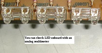
Light emitting diodes or LED is very simple to check. Just connect your analog meter probe to the pins of LED and set your meter to X1 ohm. If there is no light from the LED, just change the polarity of the probes. You can check LED while it is still in circuit.
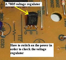
Voltage regulator can’t be check off board with multimeter because it is an IC (it has lots of components inside it). You have to switch “ON” the equipment and check the output dc voltage of the voltage regulator. First you must know what the part numbers of the voltage regulator are, and then you read the specification and locate the input and output voltage and pins. For example, the general type of voltage regulator starts with the part numbers like 7805, 7812, 7908 and etc. From the spec you would know that pin one is input, pin 2 is ground and pin 3 is output. If there is input voltage to the voltage regulator and no or low output voltage, suspect the voltage regulator itself faulty or something along the output line that dragged down the output voltage. Do you still remember from my previous article that voltage regulator can breakdown when under full load? Since the voltage regulator is easily available and cheap, just direct replace it and retest the equipment or recheck again the output voltage.
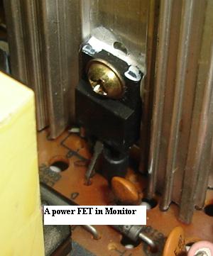
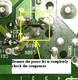
Many switch mode power supply are using the combination of a power FET and a PWM IC design to switch the power transformer. Whenever there is any power failure (fuse totally blown into dark color) one will always suspect the power FET has gave way. Usually we would use the black probe set to X 1 ohms and place it to the center pin (drain) and the red probe to the gate and the source pin. This is the same way when we want to check HOT on board. If there is a reading, chances are high that the FET has developed a short circuit. But you also have to remember that a shorted bridge rectifier may cause the power FET to have reading when check with the analog meter while it still on board.
If you get an open reading this doesn’t mean the power FET is good because a faulty FET can become open circuit too. My point to you here is that don’t waste your time checking FET onboard (if the FET shorted then you can detect right away but what if the FET open circuit?) because it is not accurate, you have no choice when comes to testing FET, you just have to remove it out from board and test it with analog meter set to X 10k ohms (refer back to my website www.electronicrepairguide.com about testing FET). This is true also if you want to check FET in the B+ circuit (B+ FET) and FET’s in the Monitor S-correction circuit.
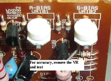
Checking variable resistor (VR) on board is not that accurate because of the back circuit besides some VR have their resistance code printed so small at the bottom of the VR. The best is still removing it out from the circuit and test it with an analog meter. Any erratic reading can be easily seen from the analog meter panel compares to using digital meter.
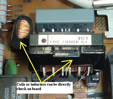
Inductor or coil testing can be done on board without removing the coil out from the circuit board. If a coil has less loops (small coil), then we can just direct measure it with our normal ohmmeter. A small coil is just like a wire or a jumper and it rarely become defective although it has some inductance value in it. Testing coils that have a bigger inductance value like the B+ coil used in Monitor circuit is different from checking the small coils. You can’t just measure the bigger coils with an ohmmeter because a bigger coils tends to develop short circuit internally that can’t be detected by a normal meter. The meter that I use to check the bigger coils is the Dick smith flyback tester. You can check the coils while it is still in the circuit. Once you know the right method of testing coils, I’m sure it won’t take you long to measure any coils in electronic board.
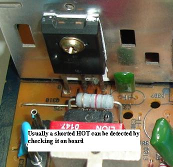
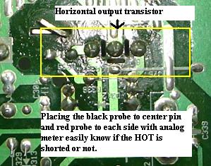
Checking horizontal output transistor is so easy and you can check it on board. Set your analog meter to X 1 ohm and place the black probe to the center pin (collector) of the HOT and the red probe to base and emitter. It should not register any reading. If there is a reading, most probably the HOT has developed a short circuit. Be aware too that components that links to the HOT like damper diode, flyback transformer, safety capacitor, B+ circuit components and if these components go shorted it could cause your analog meter to have reading. Some HOT in certain Monitor designs are difficult to open (you have to remove the whole board in order to unscrew the HOT) so to save time follow the example above.
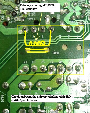
As for the switch mode power transformer (SMPT) primary winding, you can’t accurately check it with an ohms meter even if you already took it out from the board. You can only test it with a special type of coil meter or the dick smith flyback tester. You can check the primary winding of the SMPT on board without removing it out with the flyback tester. If there are any shorted components in the primary side (power fet) or in secondary side (secondary output diodes) the flyback tester will registered a shorted reading and the LED bars would not lit. Just play around with the flyback tester (if you have one) and I believe you will quickly notice how it can help you to test a winding fast. Some technicians are using the more expensive type of flyback tester such as the Sencore LC 103 capacitor and inductor analyzer to test the primary winding of SMPT.
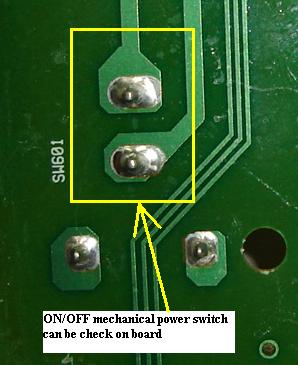
Checking the on/off power switch is the easiest one. Just place your meter probes to the switch point (assuming the power switch have 2 leads) and set your ohm meter or continuity check function. It should show a very low ohm resistance or the beeper will beep if you use the continuity checker. You can perform this test even if the power switch is still in circuit. You can also use this method to test on the micro switch.
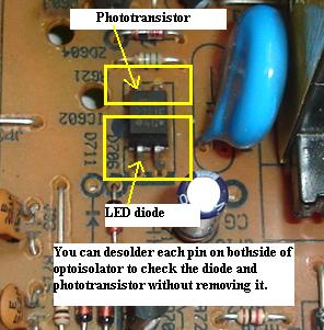
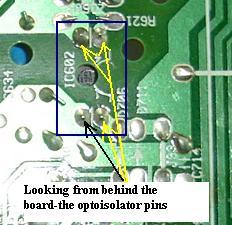
Optoisolator or optocoupler IC’s usually located in between the primary and secondary side of power supply and can be test even if the IC is still on board (you can actually test this type of IC with your multimeter). Some of the famous optocoupler part numbers are 4N25, 4N35, PC123 and etc. Just desolder one pin on each side (assuming this optocoupler have 2 pins on each side) of the optocoupler. Pin 1 and 2 is the LED light and pin 3 and 4 is the phototransistor collector and emitter. Place your analog meter probe set to X10 k ohms at pin 1 and 2 either way and it should show only one reading (low resistance reading). This is just the exact same way as when you are checking a normal diode. If it shows 2 reading most probably it had developed a short circuit. Now place your probes to pin 3 and 4 either way and again it will only show one reading (this time the resistance reading is a little bit high). If you got two readings then the internal transistor may have short circuit.
If you want to measure an optocoupler that have 6 or even 8 pins, I suggest that you search for its data first from the internet or from semiconductor data book. Once you know how the internal components are wired, then you will use the best checking method to test them individually. Remember, a shorted optoisolator can cause low power, no power or even power blink in switch mode power supply.
This is the end of part one article and part 2 will be reaching your mailbox by next week. I’ll be touching on components like the flyback transformer, capacitors, diodes, zener diode, posistor, yoke coils, transistor and many more. Have a great week my friend!
|
|
Copyright@ 2006-2014-www.ElectronicRepairGuide.com All Rights Reserved
