|
How To Build Your Own ESR Meter
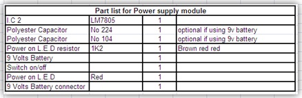
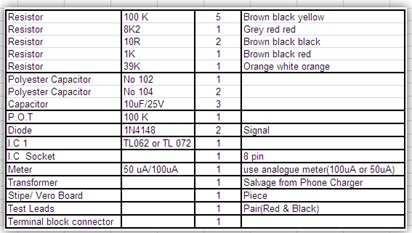
Every trade has different tools of trade, for electronics the minimum you should have include:- Multimeter(Digital & Analogue), Soldering Iron/Stand, Screw driver, Side Cutter, De-soldering pump, and Soldering Wire, These you can get them cheaply from your nearest electronics shop which I believe they are readily available. There are others which I consider very important but a bit expensive for someone who is getting started and therefore can be added later as you walk down the road of electronics repairing. These include ESR Meter, Flyback tester, Oscilloscope among others. In this article I am going to show you how you can make an ESR meter yourself by using readily available strip board/Vero board and get the same result as the professional assembled unit. The reason I introduce this kit is to enable many of our followers who are starting in electronics and find it a challenge to invest in a new ESR meter. I am sure once you add this simple but very important test equipment on your work bench you will notice an increase in the number of equipment you repair may it Television, SMPS, Monitors etc because technically speaking no electronics equipment under the sun that does not have capacitors on the circuits. From my experience in electronics (my personal opinion) I have seen that capacitors are the major cause of problems in electronics equipment especially equipment over five years. Capacitors fail in different ways and in most cases the meter (Digital or analogue) will not tell the truth about a faulty capacitor. Here is where the ESR meter comes in handy as the best friend to a technician because it speaks about the true state of the capacitor at hand by measuring the equivalent series resistance (ESR) of the capacitor under test. Equivalent series resistance (ESR) of a capacitor is considered the best parameter to know the health of an electrolytic capacitor. The circuit is divided into two parts: The power supply and the main ESR circuit. A) Power supply 5 Volts DC To assemble the power supply you need the part listed here below: Please note that the two Polyester Capacitor no 224 and 104 are not necessary if you are using 9 volts battery and therefore can be left out of the circuit.
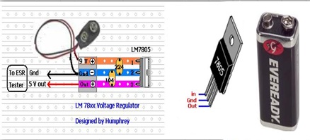
Assembly: Take a small piece of strip board and inert the I.C LM7805 the way it appears on the Picture below..The 9 Volts from the battery goes into Pin 1 of the i.c LM7805 and goes out from pin 3 as 5 volts dc. Pin 2 is ground and you should attach two wires on this pin (one goes to the battery negative and the other to the main circuit ground). The 5 Volt output is taped to power the main circuit.
B) Main ESR circuit:
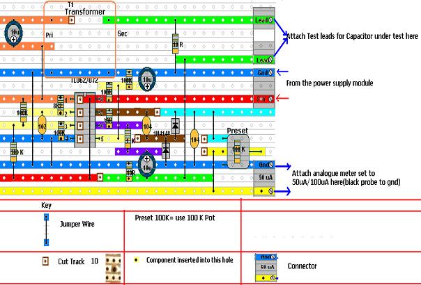
Click here for larger main circuit
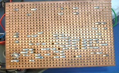
If it is possible you can print the above template with a color printer for better results and for clarity. After you finish assembling it is important you test for continuity between the 5 volts power line and the ground. It should not beep...if it beep it means there is a short on the supply line and should be sorted out before applying power. Also check for continuity between tracks to see if there is any short between any two tracks. Also make sure the Track are cut underneath according to the template and be sure to check for continuity across the Cut to see if its complete. Please note the jumper wire underneath the I.C TL062 and should be fixed first. I strongly advice to use the IC Socket 8 pin in this project and the Socket should be shouldering first for reference while installing other components. Assembly: Take one full piece of strip board and estimate where to insert ic socket in relation to the above circuit, in the example given here I have inserted the ic socket pin 4 of ic TL062 at the intersection of (7 holes high from the bottom of the strip board and 10 holes from the left hand side of the strip board) Once you install the ic socket it will guide you on installing other component in reference with this ic socket. The transformer is to be installed last. You will need to enlarge the strip board hole to inert the transformer pins. Also note the polarity of the Electrolytic Capacitors and the diodes when installing them in the circuit. For the Capacitors I have marked the positive pole and for the diode the Stripe is the cathode (negative pole) For the connectors use different color for the wire to avoid confussion. In the example above I have used green for Lead connector, red for 5 volts supply and blue (Black is better) for all ground and yellow connector for output (attach analogue meter set to 100uA or 50 uA) To install the 100K Potentiometer you need to attach three wire for the three legs so that you will not have problem fixing it to the project box. Just solder the three wires as shown on the diagram to the circuit. Component side view:
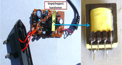
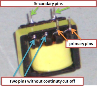
Under side view (please note the CUT) Part list for the main ESR circuit Transformer should be ferrite core, you can salvage one from the dead pc power supply/ monitors/ TVs and if you find a phone charge which uses smps transformer you can use it. Get a junk phone charger and salvage the Chopper transformer shown in the diagram above, usually it will have only two pins on the secondary side because in charging the phone only need one source (5 volts) so you will use the two pin to connect to the circuit. For the primary you will find that it will have more than two pins. Test with your meter (analogue or digital) for continuity between any two pins. The set of pins with continuity use them and for the ones without continuity just cut them off with a side cutter as shown on the diagram below. To install the Transformer: I suggest you install the transformer and the 10 ohm resistor across the transformer out secondary pins last: this is because the transformer size and pins are not standard and therefore it will depend on what you have at hand.
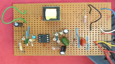
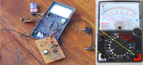
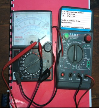
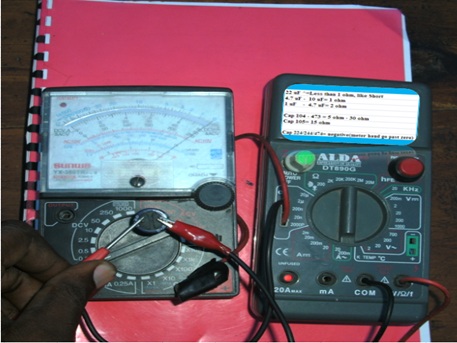
That is why I have used two long jumpers as seen on the picture above. To install the transformer pins into the strip board you may have to enlarge the hole a bit but be sure when soldering you make connection with the track. After you have finished assembling now its time to test if all is well. So don’t put the project into the project box yet. Take your power module and attach to the main circuit and attach your analogue meter set to 100uA/50uA. Setup Insert the project leads into the analogue meter has shown above and power is On. Short the project probes and adjust the zero adjust knob to zero mark on the analogue meter. If all is well up to here then you have done it and you can sit back and have some coffee for job well done. The ESR meter is ready and should be put to do the work that it knows best…Catching those Capacitors which have been giving you headache right in circuit. Capacitor under test:
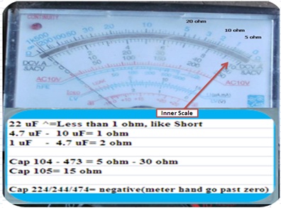
Final product In use Use the inner scale where every box represents one (1) ohm, all electrolytic capacitors should have ESR less than 2 ohm. For any electrolytic capacitor between 2 ohms and 5 ohm please consider the working voltage of that capacitor. For the example capacitor 4.7 uF/250 V used in CRT television to filter the RGB amplifier supply can read up to 5 ohms and still be okay. Same to capacitor 1uF/50 v also tend to read high. If you are in doubt you can always compare with a new one. For non electrolytic capacitors they have ESR of 5 ohms and above. On my meter capacitor 0.1uF(no104) reads 5 ohms, Capacitor no.105 reads 15 ohms and capacitor 473 reads 30 ohms. Capacitor no 224/244/474 behaves funny and the meter hand goes past the zero mark.
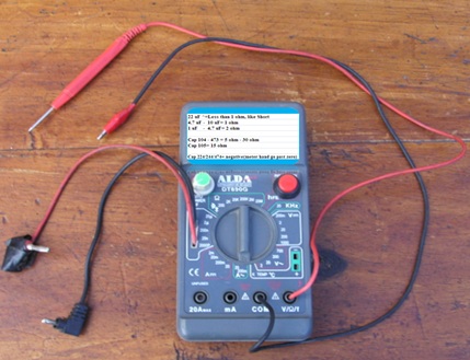
Caution: Be sure Capacitors under test are discharged. Good capacitors behaves as short and therefore a shorted capacitor(rare) will test like good with this meter and therefore always if you have any reason to doubt a reading use your analogue meter to confirm. Be sure there is no capacitor in parallel with the bad one (Lift up one out of the circuit, just one leg is good enough) Check electrolytic capacitors in-circuit- Polarity does not matter, for non electrolytic capacitors use with a pinch of salt. If you the meter hand zero adjust is unstable after using the meter for sometimes maybe the battery is low and must be replaced. Challenges: As you can see I have salvaged a junk meter box for my project housing, in my market here in Kenya getting a project box is not easy and so I had to make do with whatever is available (Junk Digital meter housing) I have also published a homemade flyback tester on my blog using Strip board and therefore if you want to build one click the link below. http://humphreykimathi.blogspot.com/2010/08/do-it-yourself-flyback-tester.html With that thank you Friends Wishing you all the best. Humphey Kimathi Author CRT Television repair Course.
Click Here to check out the latest ebook by Humphrey Kimathi
Click here to learn how you can become a Professional in Switch Mode Power Supply Repair
Click here to learn how you can become a Professional in Testing Electronic Components
Click here to learn how you can become a Professional in LCD Monitor Repair
Click here to learn how you can find burnt resistor value
Click here to Get 24 Best Electronics Repair Articles
Click here to learn Basic Electronics By Greg S Carpenter
Recommendation:
Recommended Mr Steve Cherubino Laptop Repair Videos For Beginners!
Recommended Mr Kent Projection Television Repair Membership website-Visit Now!
Recommended Mr Kent LCD TV Repair Membership website-Visit Now!
Recommended Mr Kent Plasma TV Repair Membership website-Visit Now!
|
|


Copyright@ 2006-2014-www.ElectronicRepairGuide.com All Rights Reserved